draw a arc path between two points in 3d
Preparing an AutoCAD drawing for 3D
Introduction
Information technology is extremely of import to prepare an AutoCAD drawing taking into consideration two main issues
- The cartoon should exist organised and fatigued then as not to compromise the product drawing. This means that it should be fatigued in a fashion that benefits both the AutoCAD outputs and the 3D outputs. Right layering, closed polylines created from a framework and simplified object positioning are examples of this process
- The cartoon should be organised to facilitate easy import / consign with MAX/VIZ. Keeping a handle on what elements will need to exist created as single objects in 3D and which will need to be created as i object is very important. Likewise, making the layer system easily understandable and 'object focussed' is important
This tutorial explains the main issues to consider when drawing in AutoCAD and preparing a drawing for employ in 3D work
Download Sample Data
In order to follow this tutorial, y'all may want to use the supplied files. Please read the sample information instructions earlier downloading.
kf301_files.zip (583kb)
Meridian of folio
Layers and Drawing Methods
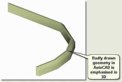
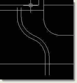
Organisation of all elements that are to exist used in 3D using layers is vital equally well equally a good knowledge of make clean, accurate drawing methods for 3D work. Call up that what looks acceptable in 2d may not work as you lot want in 3D and may expect terrible. A good example of bad drawing is the non-use of arcs in the polyline control where a curved road department is represented by a series of line segments. When turned into a kerb line in 3D it will expect like the image beneath:
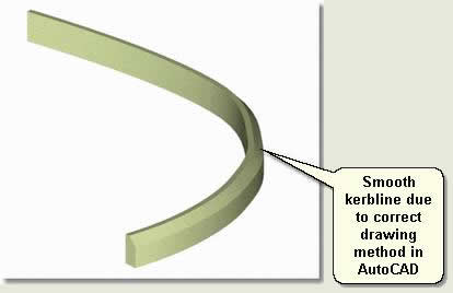
The correct drawing method (which is easier) produces a proficient looking and authentic result in 3D
Clean and Simplify Drawing
Before using an AutoCAD drawing for importing into MAX/VIZ only those elements that are going to exist used for 3D work demand keeping in the drawing. Extraneous lines and text should be removed and a 'buffer' drawing used instead of a main product drawing. The post-obit checklist should also be implemented before starting to use AutoCAD information:
- Purge the drawing of all items and nested items
- Inspect the cartoon
- Set up UCS to Globe if another has been used
- Bind Xrefs
- Detach Images
- Utilize Drawing Cleanup tools if using Autodesk Map to simplify linear features and remove duplicates etc
- Finally, brandish simply those elements that are going to be used and Re-create and Paste into a New Cartoon. Use Edit > Re-create and so Edit > Paste to Original Coordinates
Elevation of page
Layers
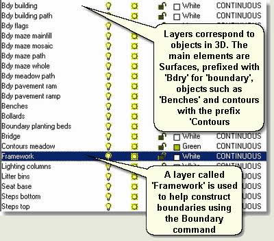
The master method of creating objects in MAX/VIZ outlined in these tutorials is to create objects from layers. This is a straight forwards process that allows yous to call back 'objects' right from the first
Open kf301_01.dwg in AutoCAD. This drawing contains an case layer system used for piece of cake import to MAX/VIZ
NOTE: Creating split objects from one layer in MAX/VIZ is handled on the import options dialogs in MAX/VIZ
Top of folio
Cartoon Methods
Expert clean cartoon techniques are essential to produce good looking scenes and benefit the drawing equally a whole. Together with a comprehensive layer system based on 'objects' and the use of airtight boundaries using a framework layer, and the boundary command, the utilize of appropriate AutoCAD tools make transition into 3D much easier. This tutorial explores some of the basic useful commands to create make clean, simple, accurate lines in AutoCAD
Notation: The creation of closed boundary polygons and comprehensive layer system is useful for other outputs from AutoCAD and 3rd political party applications. Consign to CorelDraw or Mcolour for program graphics, hatching areas in AutoCAD and listing of area quantities are skilful examples of extended functionality using these methods
TIP: Ever draw lines using the Polyline command. Using the Line command produces fragmented and less managable drawings
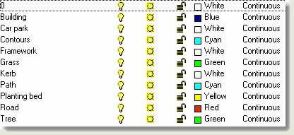
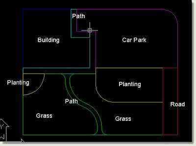
- Open up kf301_02.dwg . This drawing contains some layers for a creating surfaces and a kerb for a uncomplicated mural scheme (shown completed below)

Top of page
Building
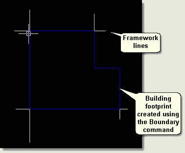
Detect that a layer called 'Framework' has been created and there are building framework lines already fatigued. These take been created using the Commencement command. The landscape drawing is synthetic by referencing the known positions of points and lines of the building - as it would be constructed on-site
- Make Building layer current
- Draw > Boundary > Option Points - choice a bespeak in the heart of the building framework lines. This creates a closed purlieus for the building on the correct layer
Notation: If the Purlieus command does not work check the following points:
- Elements such as blocks are frozen and non turned off (AutoCAD however includes off layers when searching for a boundary)
- The purlieus extents can be viewed on the screen (only graphics on the present screen display are included in the purlieus search)
- All existing polylines and framework lines are 2d at zero height (ie non 3D polylines)
- At that place are no gaps in any of the polylines
Top of folio
Automobile Park
- Make Framework layer current
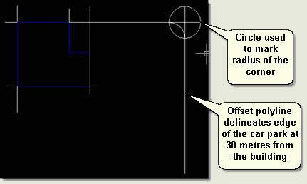
- Describe a framework polyline from the bottom right corner of the building vertically up using Ortho On (F8 toggles Ortho on>off)
- Offset this line 30 metres to the correct
- Turn OSnap On (Object Snap) and change the Snap Settings to Endpoint. Describe a horizontal polyline from the height right corner of the edifice horizontally using Ortho On so that it crosses the previously drawn polyline
- Draw a ciclcle snapped to where these lines run across with a radius of 5 metres (this value can be typed on the command line when creating the circle)
- Start drawing a framework polyline snapped from the superlative correct corner of the building with the second vertex of the polyline snapped (intersection snap) to where the circle crosses the line. Then type A at the command line (this is a polyline sub-command - look at the command line - which allows y'all to draw an arc as part of a polyline). Snap the next vertex to where the circle crosses the vertical framework line. And then type L at the control line (this takes you lot back to drawing a normal line within the polyline). Using Ortho On elevate the polyline down and consummate the polyline as shown below. This process accurately offsets the car park edge and gives a rounded corner of radius v metres
Acme of page
First Path and Road
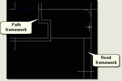
- Delete the circle
- Extend the bottom horizontal building framework line to see the new car park border framework line and Beginning the new auto park edge line left 5 metres to the left. This creates a framework line for the route
- Offset the extended framework line down two metres and the original right mitt vertical framework building line to the right 2 metres. This creates framework lines for the first path
- Trim the lines and Delete unecessary lines so the framework looks like the epitome beneath. Using Ortho On depict a framework polyline that closes the road at the lower terminate
Pinnacle of page
Grassed Expanse and Planting Beds
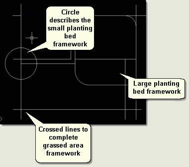
- Using Grips with Ortho On drag the left building framework line down and the line created to close the road across left so they cross
- Using Ortho On describe a polyline line starting from the corner of the path down and using the Arc sub polyline control then Line sub polyline command describe the large planting bed
Notation: Arc sub commands must just exist used afterward starting to draw a polyline in Line mode. Otherwise the arc 'balloons' due to it not having any management
- In the left corner of the grassed area framework create a circle snapped to the edge corner of the path framework to describe the pocket-size planting bed
Summit of page
Second Path
- Draw a polyline using the Arc sub command and Line sub command to describe the centre line of the 2nd path
- Outset this line 0.75 metres to the left and 0.75 metres to the right
- Delete the center polyline to give an initial framework for the second path
- To splay the entrance points to the path Trim both ends of the path:
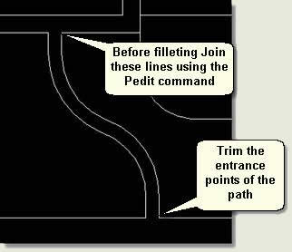
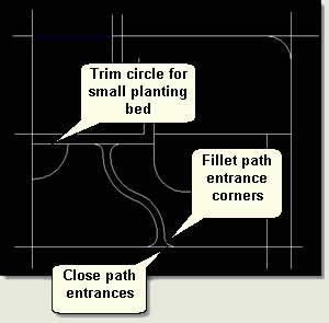
- Finally (to complete the framework) Fillet the corners or the path entrances. Earlier filleting, Join the framework polylines using Pedit then utilize the Fillet control to create a fillet of radius 2 metres at each corner. Then use Snaps to snap a polyline to close the path ends
- Trim the circumvolve for the small planting bed so the lines exercise not interfere with the cosmos of boundaries
Peak of page
Create Surface Boundaries
Making each layer current in turn utilise the Boundary command to quickly create boundaries for each element
Plough the Framework layer off
Top of page
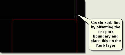
Create Kerb Line
- Offset the Auto Park boundary by 0.xv metres
- Select the offset polyline and place on the Kerb layer by selecting the Kerb Layer in the Layer Dropdown List and so pressing Esc twice. This layer will be turned off before importing into MAX/VIZ as edges are created from the purlieus lines using the Loft compound object
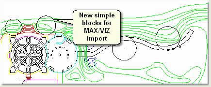
This minor tutorial shows how simple the geometry should exist when importing to MAX/VIZ. The drawing should contain no edge information apart from the closed boundaries that delineate all surfaces seamlessly (the subject of this tutorial). Secondly, objects such as trees, benches, lamp posts etc should be represented by simple circle and rectangular blocks on the right layers. These simple 2D blocks are replaced in MAX/VIZ with 3D objects, merely are positioned in AutoCAD. Thirdly, 3D landform information in the form of contours, 3D polylines (strings) or a triangulated mesh is needed in order to transform the 2D plan into a 3D scene
Notation: This sequence of tutorial files has been saved as four drawings: kf301_02a/b/c/d.dwg for reference
Checklist of Commands
Become very familiar with the following commands which were all used to chop-chop and accurately create this simple mural plan. More complicated plans merely repeat these commands over and over again
Movement
Rotate
Copy and Multiple Copy
Offset
Trim
Extend
Boundary
Fillet > Chamfer
Pedit
Manipulation of Vertex Handles
Snap Fashion On>Off and Snap Settings
Ortho
Elevation of page
Simplify Blocks
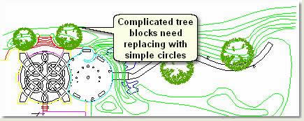
Complicated 2D blocks should non be imported into MAX/VIZ if they are merely used as markers for 3D Objects or as objects for replacing with 3D objects. Replacing blocks with much simpler blocks before importing into MAX/VIZ is straightforward in AutoCAD using the Reference Edit dialog
- Open up kf301_03.dwg. This drawing contains four detailed graphic blocks for trees which need simplifying by replacing them with circles
- Select i of the blocks (they are even so block reference) and double left click. This opens the Reference Edit dialog
Annotation: The Reference Edit dialog is a feature of AutoCAD 2004 plus. Replacing blocks in previous versions of AutoCAD entails 'redefining blocks'
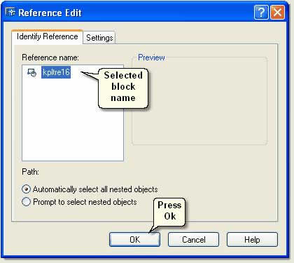
- Printing Ok to isolate the cake and open it up for editing. A pocket-sized toolbar appears and but the block is available for editing. All other blocks of the same name disappear and all other elements in the cartoon turn grayness
- Zoom to the block and draw a circle in the same position and at the same size as the tree block
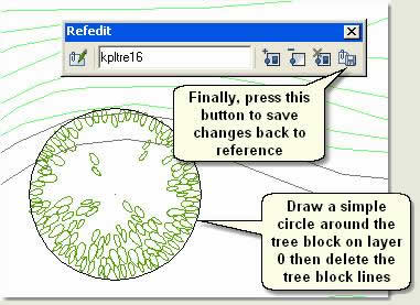
- Draw a circle around the tree block on layer 0, then delete the tree block lines
- Press the Save back changes to reference push to supervene upon all references of the block with a simple circumvolve
TIP: Another pick for replacing blocks can be found on the Limited Bill of fare/Blocks. Use Supplant block with some other block to rapidly replace a cake in the drawing with another
Top of page
Import Options
Earlier importing data from AutoCAD into MAX/VIZ ii issues must be addressed
- If the cartoon has been created far from 0,0 on the X and Y axes, the cartoon data needs to be moved closer to 0,0. This improves how MAX/VIZ handles the data in the later stages and makes sure the modelling is accurate and any blitheness smooth
- The relationship betwixt the layers and how they are configured to create objects on import needs to be understood. So simple routines using i of two separate import dialogs can be used to update the MAX/VIZ scene at whatever fourth dimension
This section explains how to separate drawing data for MAX/VIZ from the product design drawings and how to configure the Import dialog for easy update of the scene from AutoCAD
NOTE: If cartoon units are in millimeters, and then also re-scale the drawing at this phase (it is not advisable to keep in millimeters for a mural scale projection)
Top of folio
Move to Nil
If AutoCAD geometry is created far from zero, then accuracy bug may occur when modelling this data in MAX/VIZ. This is due to the fact that AutoCAD is authentic to 64 decimal places, whereas MAX/VIZ is only (just?) accurate to 32 decimal places. The problem normally manifests itself when animating cameras along paths when 'camera shake' will occur. Large bounding boxes around objects are also a problem if the AutoCAD information is far from nada because the bounding boxes start at 0,0
AutoCAD drawings created far from zero are usually the issue of using Ordnance Survey basemap information to starting time the drawing process. Virtually basemap tiles are hundreds of thousands of metres abroad from zero on the 10 and Y airplane. Needless to say, landscape drawings are often created far from naught
- Either move the basemaps to zero before creating the cartoon and in the knowledge that other data need non be added in a 'mapped' environment or use a carve up drawing for 3D work with a known basepoint for moving geometry to cypher thus:
- Open up and manage a new separate cartoon for importing into MAX/VIZ
- Import the following three elements needed for visualisation work into this new drawing: Closed boundary lines delineating all surfaces / Simple blocks for objects / Landform information in the form of Contours, 3D polylines (strings) or Triangulated Mesh or Grid
TIP: Utilize Autodesk Map 3D to attach the project pattern cartoon to the MAX/VIZ drawing and employ unproblematic layer property queries to add elements to the MAX/VIZ cartoon at any time. This is a very effective method of filtering just the data needed for 3D piece of work whilst keeping separate from the production drawings. Information technology allows the original blueprint cartoon to be changed without having to worry about layers on>off and layers that are not relevant to 3D work (drawing for 3D piece of work should be very straight forward and most simplistic). Complicated blocks for copse, seats, lamp posts etc tin can even be replaced with simple blocks as function of the process. Irresolute 2nd plans using GIS functionality and visualising these scenarios in 3D is another reward of using Autodesk Map 3D with MAX/VIZ
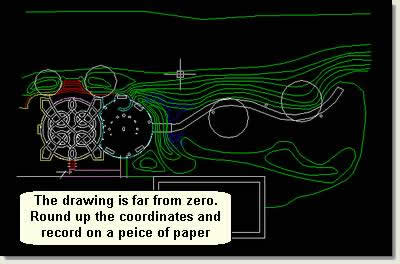
- Open up kf301_04.dwg . This drawing is an example of a drawing containing these 3 elements. However, if you look at the coordinates of the data on the Satus Bar y'all will find that it is far from cypher
![]()
Round these coordinates upwardly to 320000,456000
- Zoom out and tape on a peice of paper the rounded upward coordinates preferably to the lesser left of the site. The rounded up coordinates would be 320000, 456000 in this case. This happens to be in the heart of the scheme, simply this is Ok
- Turn on and unfreeze all layers
- Select all the elements in the cartoon and employ the Move command to move the data to zero thus:
- When prompted for the base signal or displacement type 320000,456000 on the command line so Render
- When prompted for the second point of displacement type 0,0 on the command line then Return. This moves the information from a known recorded point to 0,0
TIP: Another method involves drawing a rectangle effectually the site (on a layer that tin can be frozen) and using the bottom left corner of the rectangle as the move base bespeak
The drawing is now fix for import into MAX/VIZ without whatever problems connected to being sited far from zero. Repeat this routine to move whatsoever new data from the original 2D blueprint drawing
Height of page
Import AutoCAD Drawing Dialogs
To control how AutoCAD information is imported into MAX/VIZ ane of 2 Import Drawing dialogs is used depending on how the data has been organised in AutoCAD and how the objects need to be organised in MAX/VIZ
Importing using the Legacy AutoCAD dialog
This dialog is the 'sometime' version but does have some useful features
- Yous can import text
- Objects are named the same as the layer they were created on in AutoCAD to aid with object organisation
- Reset MAX/VIZ
- File > Import. On the Select File to Import dialog change the Files of Blazon to Legacy AutoCAD (*DWG). Select kf301_05.dwg so Open
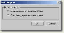
- On the Dwg Import dialog select Merge and press Ok
- On the Import AutoCAD Dwg File dialog cheque the following:
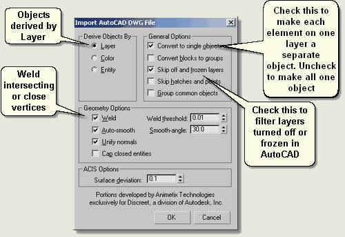
- Printing Ok
- In the Select past Name dialog notation that all the layers take been turned into objects and that all the steps, for instance, are one object. This is Ok for some objects, but not others. It is handy for the contours to be imported like this. Then likewise the positioning blocks for landscape objects such as bollards, seating and lamp posts. Still, objects such as the steps need to be imported as separate objects. To import those objects that have been imported incorrectly delete the objects and re-import having changed the import settings as follows:
- Delete S teps bottom.01, Steps top.01, Sundial.01 and Wall.01
Importing using the AutoCAD Drawing dialog
This dialog is the most recent version and has other useful features
- Y'all tin select objects on layers you lot desire to import from a layer list
- Objects, however, are not renamed but organised in layers in MAX/VIZ
- File > Import. On the Select File to Import dialog change the Files of Blazon to AutoCAD Drawing (* . DWG ,*.DXF ). Select kf301_05.dwg and so Open
- On The Layers Tab choose Select from list and select the following layers:
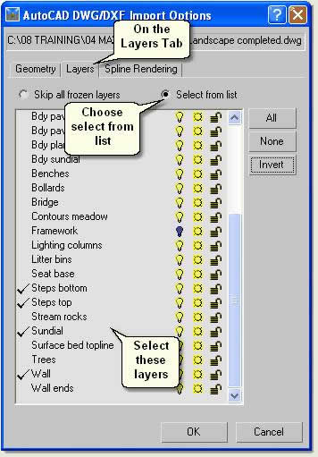
- On the Geometry Tab select the following options:
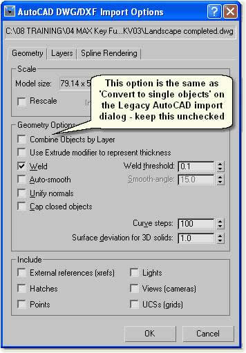
- Press Ok to import the objects into MAX/VIZ
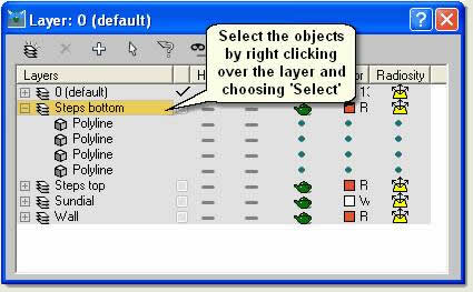
- Detect that the all objects have been named 'polyline' ie as the object 'type'. Use the Layer dialog and Rename dialog to organise the objects farther:
- Open up the Layer dialog and right click over Steps bottom. Choose Select from the right click menu. This selects all the bottom step purlieus lines
TIP: If the Layer dialog is not displaying correct click on the principal toolbar (non on an icon) and select Layers from the listing
- Tools > Rename Objects. On the Rename dialog type in the Base Name, check 'Numbered' and set the Base Number to 1
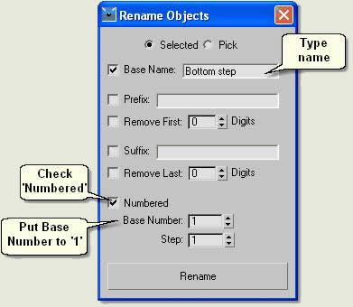
- Press Rename to rename all the objects selected
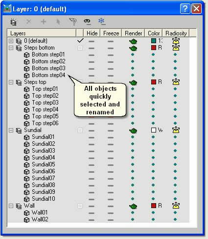
All objects are now in the correct format and named correctly in order to make the modelling process easier
Meridian of page
Donate to CADTutor
If you found this tutorial useful, y'all might like to consider making a donation. All content on this site is provided free of charge and we promise to keep it that way. However, running a site like CADTutor does toll money and you can assistance to improve the service and to guarantee its futurity past donating a small amount. We guess that you probably wouldn't miss $v.00 only information technology would make all the difference to the states.
Source: https://www.cadtutor.net/tutorials/3ds-max/prepare-autocad-drawing.php
Post a Comment for "draw a arc path between two points in 3d"